Multivibrator are sequential logic circuits that operate continuously
between two distinct states of high and low
Multivibrator are can also classified depending on the coupling also.
· Collector coupled multivibrator
1. Astable multivibrator
2. Monostable multivibrator
3. Bistable multivibrator
1. Schmitt trigger
· Emitter coupled multivibrator are more stable
than collector coupled ,but have less variation than collector coupled
multivibrators
Astable multivibrator
·
It is free running multivibrator
·
It does not have any stable states
·
It has two quasistable states
·
It doesn’t require triggering pulses.
·
The duration of two quasistable state is
dependent upon the two rc time constants.
·
Total time period = t1 + t2
= 0.69 R1 C1 + 0.69 R1 C1
=1.38 R1 C1
·
Frequency = 1/(time period)
= 1/(1.38 R1 C1)
·
Duty cycle = t1 / ( t 1+t2
) =
50%
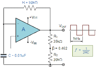
ASTABLE MULTIVIBRATOR USING OP-AMP:
· Vi = - β Vsat
· Vi = - β Vsat
· Charging time T1 = RC ln( (1+ β) / (1- β) )
· Total time period of output wave form T = 2T1
= 2RC ln( (1+ β) / (1- β) )
= 2RC ln( (1+(2R2) / R1 )
· Frequency = 1/T
· R1 = 1.16 R2
· frequency = 1/(2RC)
DUTY CYCLE:
Duty Cycle = (RA + RB) / (RA + 2RB)
if the duty cycle is less than the 50% then the diode is place across RB
Duty Cycle = (RA + RB) / (RA + 2RB)
if the duty cycle is less than the 50% then the diode is place across RB
Frequency is independent of supply voltage
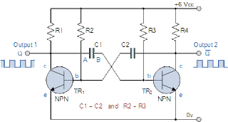
ASTABLE
MULTIVIRATOR USING TRANSISTOR
·
It is
free running multivibrator
·
It
does not have any stable states
·
It
has two quasistable states
·
It
doesn’t require triggering pulses.
Total time period = T1 + T2
=0.69 R1C1 + 0.69 R1C1
= 1.38 R1C1
Frequency of astable multivibrator= 1/time period
= 1/ 1.38 R1C1
Monostable multivibrator
·
It has one stable state & one
quasi-stable state
·
When triggering pulse pulse is applied it
enters quasi-satble state from stable state.
·
It is also called as a single shot
multivibrator
·
The pulse width of monostable multivibrator
is
t = 0.69 RC
Bistable multivibrator
·
In bistable multivibrator resistor coupling
is used between the two transistor stages
·
It has two stable states. By triggering the
output it can be change from one state to another i.e. from low to high or high
to low
·
Triggering pulses are given to the base of
transistor
·
Transition time is the time taken for the off
transition to on state immediately whenever we applied triggering signal to it.
·
Commutating capacitors or speed up capacitors
are used to reduce the transition time.
Triggering:
We
have two types of triggering are there
·
Symmetrical
triggering: in symmetrical triggering method triggering pulses are
taken from single source
·
Asymmetrical
triggering: triggering signals are taken from different
signal sources

