It is the mathematical representation of graph in the form of matrix
An incidence matrix describes the way a circuit is connected. Incidence matrix specifies the orientation of each branch in the graph and nodes at which this branch is incident. Incident matrix includes all the branches of a graph as columns and all the nodes of graph as rows.
· The no. Of rows of incidence matrix is equal to no. Of nodes
· No. Of columns of incidence matrix is equal to no. Of branches
· Incidence Matrix entry is always values those are -1 , 0 , +1
Entry of incidence matrix
· If the branch is incident(towards node) on a node -1
· If the branch is pointing away from node +1
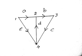
The detailed and entry of matrix values are explained through a these simple graph. That graph is shown in below fig.
 |
| Incidence Matrix Representation Graph |
while filling the matrix and doing calculations we should remember these points.
· If the branch is incident(towards node) on a node -1
· If the branch is pointing away from node +1
· If branch is not connected to node 0
The below table shows the entry of values.
a
|
b
|
c
|
d
|
e
| |
1
|
+1
|
0
|
0
|
0
|
+1
|
2
|
-1
|
+1
|
0
|
-1
|
0
|
3
|
0
|
-1
|
+1
|
0
|
0
|
4
|
0
|
0
|
-1
|
+1
|
-1
|
In the table
· 1, 2, 3, 4 represents the Nodes
· a, b, c, d, e represents the branches
Properties of incidence matrix
1. The algebraic sum of all elements of any column is zero
2. Determinant of incidence matrix of closed loop is always zero
3. The order of incidence matrix is = n*b
4. The rank of matrix is n-1 (n = no. Of nodes)
Two graphs having same incidence matrix are called “isomorphic”
Reduced Incidence Matrix
The matrix obtained after removal of one line (row) from the incidence matrix is called “reduced incidence matrix”.
If any one of the row of an incidence matrix removed then it became Reduced incidence matrix.
Order of reduced incidence matrix = (n-1) * b
The below fig is as above fig but it is only one difference. That is in the above fig having four rows here we removed one rows i.e. last 4th row.
a
|
b
|
c
|
d
|
e
| |
1
|
+1
|
0
|
0
|
0
|
+1
|
2
|
-1
|
+1
|
0
|
-1
|
0
|
3
|
0
|
-1
|
+1
|
0
|
0
|
In the table
· 1, 2, 3, 4 represents the Nodes
· a, b, c, d, e represents the branches
No.of possible tree for a graph can be given by T= Det [ A(A)t]
In the above formula
A = reduced incidence matrix
At = transpose of reduce incidence matrix
-------------- CUT SET -----------
It is the group of branch containing only one twing and no. of links.
Given connected graph, a set of its branches is said to constitute a cut-set if its removal separates the remaining portion of the network into two parts
 |
| Cut Set Matrix Representation of Graph |
Fundamental Cut Set
it is the group of branch containing only one twing and minimum no. Of links
The no. of fundamental cut sets of graph is equal to no. Of twings = n-1
Fundamental cut set matrix
It is nothing but representation of fundamental cut set in matrix form .here the
· Rows are equal to no. of fundamental cut sets
· No. of columns are equal to no. Of branches.
Orientation of the cut set matrix is same as the direction of twings related to it
1. +1 entry in the matrix is if orientation of branch is same as the orientation of cut sets related to it.
2. +1 entry in the matrix is if orientation of branch is oppositive to the orientation of cut sets related to it.
3. 0 if cut set not related to it.
 |
| Cut-Set Representation Graph |
a
|
b
|
c
|
d
|
e
| |
C 1
|
+1
|
0
|
0
|
0
|
+1
|
C 2
|
0
|
+1
|
-1
|
0
|
0
|
C 3
|
0
|
0
|
+1
|
0
|
-1
|
In the table
· C1, C2, C3 represents the Fundamental Cut sets
· a, b, c, d, e represents the branches
Note:
· Rows are used to determine the KCL eq’n
· No. of KCL eq’n for a given graph are equal to no. of fundamental outset
· The fundamental cut set matrix can be used to write KCL eq’n for given network.
1. From c1 (row) = Ia + Ie =0
2. C2 = Ib – Ic = 0
3. C3 = -Ic + Id – Ie = 0
-------------TIE SET--------------
It is the group of branches containing only one link and no. of twings
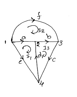
 |
| Tie-Set Representation Graph |
Fundamental Tie-Set
It is the collection of branches containing only one link and minimum no. Of twings
Important
No. Of fundamental sets for a graph
= no. Of links
= no. Of KVL (mesh equation)
L= b – n + 1
Fundamental Tie-Set matrix
§ Orientation of loop is same as the link
§ The column of matrix is no.of branches
§ The row of matrix is equal to no. Of tie-sets
Entry in matrix
+1 = orientation of branch is same as orientation of loop current
-1 = orientation of branch is oppositive to orientation of loop current
0 = branch is not related to the loop.
 |
| Tie-Set Representation Graph |
a
|
b
|
c
|
d
|
e
|
f
| |
i 1
|
+1
|
0
|
0
|
-1
|
-1
|
0
|
i 2
|
-1
|
-1
|
0
|
0
|
0
|
+1
|
i 3
|
0
|
+1
|
+1
|
+1
|
0
|
0
|
In the table
· i1, i2, i3 represents the Ti-sets
· a, b, c, d, e, f represents the branches
From that matrix we will take equations. Suppose, example from row one we will take
Va – Vd - Ve =0 like this we will take equation’s from that matrix.
Important
1. KVL eq’n can be obtained from the rows
2. Branch current can be obtained from column of matrix
3. In the fundamental cut set twing can never repeat in set but link can repeat it
4. In tie set link can never repeat but twing can repeat.