Oscillators is device or circuit it can
produce a continuous wave from without giving any input to that.
· Crystal oscillators
RC – PHASE SHIFT OSCILLATOR USING BJT
Collipt’s Oscillator’s
In oscillator oscillations are produced
by satisfying the conditions of barkhausten criterion to sustain the frequency
of oscillations.
· The loop gain i.e. Aβ must be equal to ‘1’ ( Aβ = 1)
· But practically it is slightly greater
than are equals to 1 (Aβ ≥ 1)
· The total phase shift introduced must
be zero or integral multiplies of 2π.
We have following types of oscillators
are there. Those are
· RC phase shift oscillators
· Wein bridge oscillator
· LC oscillator
· Hartely oscillator
· Colpitts oscillators
RC-PHASE SHIFT OSCILLATORS:
In RC-phase shift oscillators having three RC combinations
in it’s feedback path Each RC combination can produce 600 phase
shift so overall 1800 produces. In order to satisfy barkhausten
criterion, forward path consisting of a inverting amplifier which also provides
the phase shift of another 1800 phase shif.
Then the total phase shift around the circuit is 3600 the
below fig shows the simple RC phase shift network
The above fig shows the feedback path of RC-phase
shift Oscillator.
The above fig shows the negative feedback RC-phase shift
oscillator. Because, feedback path is connected to negative terminal in order
to get 1800 phase shift.
· W0 = 𝟏/ 𝑹𝑪√𝟔
· F0 = 𝟏/ 𝟐𝝅𝑹𝑪√𝟔
· β = -1/29
· forward path gain A=
-Rf / R
By barkhausten criterion
· |A β | ≥ 1
· (-Rf /
R) * (-1/29) ≥ 1
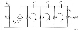
CE amplifier is an inverting amplifier which can be
used to construct phase shift oscillator as shown in below. The feedback
voltage is used as a Voltage Shunt Feedback
In the above circuit biasing resistors R1 &
R2 are very large.which makes the input resistance of CE is
very high. The transistor is replaced by simplified model with the assumption
that hoeRc≤ 0.1. the resistor R=
R3 + Rin
The frequency of oscillations are given
by For made up of BJT oscillators
· w0 = 𝟏/𝑹𝑪√𝟔+𝟒 𝒌
· F0 = 𝟏/ 𝟐𝝅𝑹𝑪√𝟔+𝟒 𝒌 ( k = Rc
/ R )
· K value is
approximately = 2.7
· (hfe)min =
44.5
·
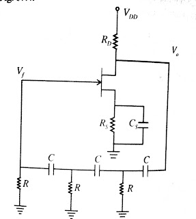
RC – PHASE SHIFT USING FET
Common source amplifier
is a inverting amplifier which can be used to construct a phase shift
oscillator as shown in fig.
The JFET phase shift oscillator uses the RC phase
shift feedback network described. The frequency of oscillations is w0 = 𝟏/𝑹𝑪√𝟔. The forward path gain
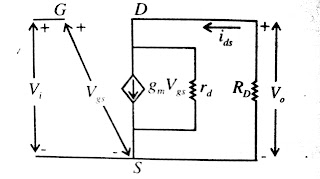
of amplifier can be obtained by the ac analysis of common source transistor. In
CS ac analysis of amplifier source capacitance Cs is
short circuited and JFET is replace by small signal equivalent diagrams as
shown in below fig.
· Output voltage V0 =
(-gmrdRDVi ) / (RD +
rd)
· Trans conductance gm =
29 / RD
· Voltage gain Av =
(Vo / Vi )
= (-
gmrdRD) / (RD + rd)
· If rd less
than RD
Av = -gmRD
· β = -1/29
· f0 = 𝟏 / 𝟐𝝅𝑹𝑪√𝟔
Wien bridge oscillator:
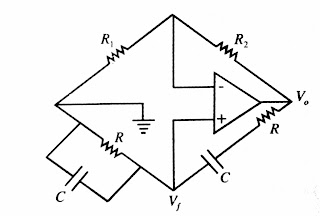
Non-inverting op-amp in
forward path and RC n/w in the feedback path form a wien bridge oscillator as
shown in below fig.
At frequency of oscillator RC n/w in
feedback path will not produce any phase shift.
· Wien bridge oscillator produces 10HZ to 1MHZ range of frequencies.
· Wien bridge oscillator having both positive feedback &
negative feedbacks.
· Wien bridge oscillator generates zero 00 phase
shift oscillations.
The below fig shows the wien bridge
oscillator
· Feedback
factor of wien bridge oscillator is
β = (R2C1) / (R1C1 + R2C2 + R2C1)
β = (R2C1) / (R1C1 + R2C2 + R2C1)
· Lower cutoff frequency of wien bridge
oscillator
FL = 1/(2πR2C1)
· Higher cutoff frequency of wien bridge oscillator
FH = 1/(2πR1C2)
· F0 =
1/(2π√(R1C1 + R2C2 )
· β = 1/3
· A=(1+ R2 /
R1)
· A β ≥ 1
· R2 ≥
2R1
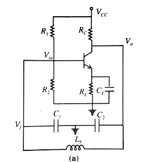
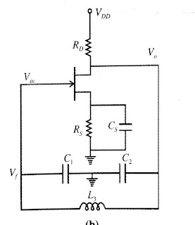
Collipt’s Oscillator’s
Collipt’s oscillators’
fig is as shown in below fig.
Fig.a) using BJT
Fig.b) using FET
· F
= 1/(2π√(LCT )
· C = C1C2 /
(C1 + C2)
· β = C1 / C2
· AVmin =
1/β = C2 /
C1
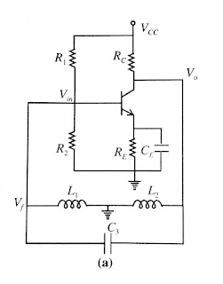
HARTELY OSCILLATOR
· F
= 1/(2π√(LCT )
· C = L1 +
L2 + 2M
· β = L2 / L1
· AVmin =
-1/β = L1 /
L2
· If they
gave mutual inductance the AVmin is changed.
AVmin = 1/β = (L1+M) / (L2+M)
Crystal Oscillators:
Crystal oscillators full fill the criteria of food accuracy
and stability of the frequency of oscillations. Quartz crystals are used for
Crystal oscillators which exhibit the piezoelectric effect. When ac
voltage is applied to the across the Crystal it vibrates at a frequency of
applied voltage. Conversely if it is vibrated it generates an ac voltage of
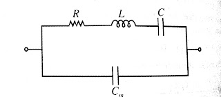
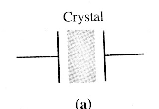
frequency same as the frequency of vibration. Quartz Crystal symbol and circut
model as shown in below.
A Quart
crystal is mounted between two metallic plates which results in mounting
capacitor connected in parallel with series RLC connection in circuit
model.
· Rochellist
has excellent piezoelectric effect. But , it has poor mechanical strength.
· Tourmaline
has poor piezoelectric effect. But, it has excellent mechanical strength.
· So we
use quartz. Quartz has good capabilities of those both.


